動作確認環境
- Cisco C891FJ-K9
- IOS 15.9(3)M10
BGP の network 設定の動作仕様とは
Cisco ルータの BGP における network 設定の動作仕様は以下の通りです。
- 自身が持つ BGP 以外のルートを BGP ルートとして BGP テーブルに追加し、BGP ネイバーに追加的にルート広報するためのコマンド
- コネクテッド、スタティック、またはBGP以外の動的ルーティングで学習したルートが対象となる
- 実際に BGP テーブルに対象ルートを追加するためには自身のルーティングテーブルに対象ルートが存在している必要がある(宛先ネットワークアドレス、サブネットマスクが一致しているルートが存在する必要がある)
上記の通り network コマンドは BGP 以外のルートを BGP ルートとしてネイバーに広報したい場合に設定します。感覚的には個別のルートを指定して BGP にルートを再配送するような感覚です。
※ただし実際の再配送設定は別に存在するため、再配送とは異なる設定として理解してください
BGP において自身からネイバーに広報される対象ルートとしては、他ネイバーから受信した BGP ルートと自身を生成元とする BGP ルートが対象となります。network コマンドを設定することで自身を生成元とする BGP ルートを追加することができる、ということになります。
※iBGPにおいてはスプリットホライズンが動作する点に注意してください
Web 上には network コマンドの指定対象ルートの説明として「自身のAS内のルート」を前提として説明しているサイトもありますが、何か条件があるわけではないのでこの言葉を気にする必要はありません。動作仕様は上記ボックス内に記載の通りです。
BGP においては network コマンドで指定したルートのみがネイバーに広報されるわけではなく、ネイバーから受信した BGP ルートに加えて network コマンドで指定したルートが別のネイバーに広報されるという動作になります。
network コマンドについて、BGP においては BGP テーブルにルートを追加する意味にになりますが、OSPF や EIGRP ではルーティングプロトコルを有効化するインターフェースを指定する意味になります。同じ network コマンドでも BGP とその他のプロトコルで意味が変わるため注意してください。
network コマンドの動作確認
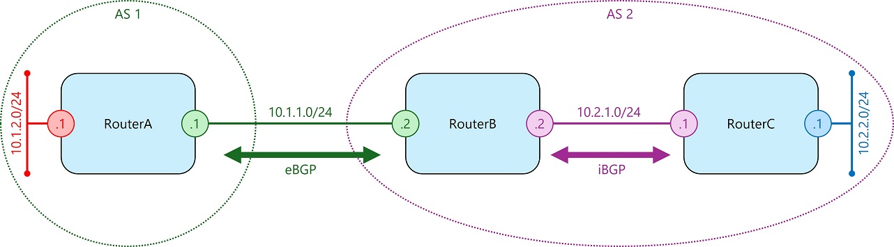
ここで以下の構成を例に BGP におけるルート広報内容と network 設定が与える影響を確認してみます。
- RouterA
- BGP AS 1 に属します
- RouterB と eBGP を形成します
- 背後にネットワーク 10.1.2.0/24 が存在します
- RouterB
- BGP AS 2 に属します
- RouterA と eBGP を形成します
- RouterC と iBGP を形成します
- RouterC
- BGP AS 2 に属します
- RouterB と iBGP を形成します
- 背後にネットワーク 10.2.2.0/24 が存在します
- RouterA 背後のネットワーク 10.1.2.0/24 は RouterA の Loopback インターフェースで再現しています
- RouterC 背後のネットワーク 10.2.2.0/24 は RouterC の Loopback インターフェースで再現しています
ここでは検証のためにまず BGP ネイバーを形成するのみの設定を行い、すべてのルータで network コマンドの設定はしないことにします。各ルータの BGP 関連設定は以下の通りです。
router bgp 1
 bgp log-neighbor-changes
 neighbor 10.1.1.2 remote-as 2
 neighbor 10.1.1.2 next-hop-self

※iBGPネイバーには next-hop-self を入れています
router bgp 2
bgp log-neighbor-changes
neighbor 10.1.1.1 remote-as 1
neighbor 10.2.1.1 remote-as 2
neighbor 10.2.1.1 next-hop-self
※iBGPネイバーには next-hop-self を入れていますrouter bgp 2
bgp log-neighbor-changes
neighbor 10.2.1.2 remote-as 2この設定内容の場合の各ルータの BGP テーブル及びルーティングテーブルは以下の通りです。
RouterA#show ip bgp summary
BGP router identifier 10.1.2.1, local AS number 1
BGP table version is 5, main routing table version 5

Neighbor        V           AS MsgRcvd MsgSent   TblVer  InQ OutQ Up/Down  State/PfxRcd
10.1.1.2        4            2     138     138        5    0    0 02:01:35        0
RouterA#
RouterA#show ip bgp
RouterA#
RouterA#show ip route
(中略)
      10.0.0.0/8 is variably subnetted, 4 subnets, 2 masks
C        10.1.1.0/24 is directly connected, Vlan11
L        10.1.1.1/32 is directly connected, Vlan11
C        10.1.2.0/24 is directly connected, Loopback0
L        10.1.2.1/32 is directly connected, Loopback0
RouterB#show ip bgp summary
BGP router identifier 192.168.179.150, local AS number 2
BGP table version is 5, main routing table version 5
Neighbor V AS MsgRcvd MsgSent TblVer InQ OutQ Up/Down State/PfxRcd
10.1.1.1 4 1 138 138 5 0 0 02:02:14 0
10.2.1.1 4 2 137 139 5 0 0 02:01:41 0
RouterB#
RouterB#show ip bgp
RouterB#
RouterB#show ip route
(中略)
10.0.0.0/8 is variably subnetted, 4 subnets, 2 masks
C 10.1.1.0/24 is directly connected, Vlan11
L 10.1.1.2/32 is directly connected, Vlan11
C 10.2.1.0/24 is directly connected, GigabitEthernet8
L 10.2.1.2/32 is directly connected, GigabitEthernet8RouterC#show ip bgp summary
BGP router identifier 10.2.2.1, local AS number 2
BGP table version is 5, main routing table version 5
Neighbor V AS MsgRcvd MsgSent TblVer InQ OutQ Up/Down State/PfxRcd
10.2.1.2 4 2 140 137 5 0 0 02:01:56 0
RouterC#
RouterC#show ip bgp
RouterC#
RouterC#show ip route
(中略)
10.0.0.0/8 is variably subnetted, 4 subnets, 2 masks
C 10.2.1.0/24 is directly connected, Vlan2
L 10.2.1.1/32 is directly connected, Vlan2
C 10.2.2.0/24 is directly connected, Loopback0
L 10.2.2.1/32 is directly connected, Loopback0どのルータでも network 等の BGP ルートを追加する設定をしていないため、すべてのルータで BGP テーブルは空になり、ルーティングテーブルにおいても BGP ルートは存在していません。
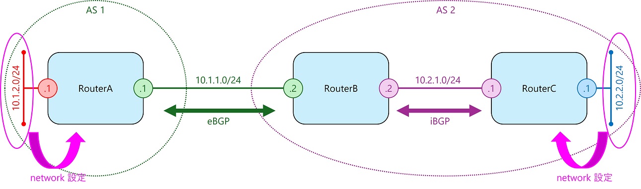
RouterA、RouterC の背後にあるネットワークへのルートを BGP に広報する
次に RouterA、RouterC 背後のネットワーク宛ルートを BGP に追加するため以下の network 設定を追加します。
- RouterA
- 10.1.2.0/24 を network 設定に追加
- RouterC
- 10.2.2.0/24 を network 設定に追加
追加するコンフィグは以下の通りです。
router bgp 1
 network 10.1.2.0 mask 255.255.255.0
router bgp 2
network 10.2.2.0 mask 255.255.255.0結果として各ルータの BGP 関連設定は以下の通りになります。
router bgp 1
 bgp log-neighbor-changes
 network 10.1.2.0 mask 255.255.255.0
 neighbor 10.1.1.2 remote-as 2
 neighbor 10.1.1.2 next-hop-self
router bgp 2
bgp log-neighbor-changes
neighbor 10.1.1.1 remote-as 1
neighbor 10.2.1.1 remote-as 2
neighbor 10.2.1.1 next-hop-selfrouter bgp 2
bgp log-neighbor-changes
network 10.2.2.0 mask 255.255.255.0
neighbor 10.2.1.2 remote-as 2この設定内容の場合の各ルータの BGP テーブル及びルーティングテーブルは以下の通りです。
RouterA#show ip bgp
(中略)
     Network          Next Hop            Metric LocPrf Weight Path
 *>   10.1.2.0/24      0.0.0.0                  0         32768 i
 *>   10.2.2.0/24      10.1.1.2                               0 2 i
RouterA#
RouterA#show ip route
(中略)
      10.0.0.0/8 is variably subnetted, 5 subnets, 2 masks
C        10.1.1.0/24 is directly connected, Vlan11
L        10.1.1.1/32 is directly connected, Vlan11
C        10.1.2.0/24 is directly connected, Loopback0
L        10.1.2.1/32 is directly connected, Loopback0
B        10.2.2.0/24 [20/0] via 10.1.1.2, 00:03:48
RouterB#show ip bgp
(中略)
Network Next Hop Metric LocPrf Weight Path
*> 10.1.2.0/24 10.1.1.1 0 0 1 i
*>i 10.2.2.0/24 10.2.1.1 0 100 0 i
RouterB#
RouterB#show ip route
(中略)
10.0.0.0/8 is variably subnetted, 6 subnets, 2 masks
C 10.1.1.0/24 is directly connected, Vlan11
L 10.1.1.2/32 is directly connected, Vlan11
B 10.1.2.0/24 [20/0] via 10.1.1.1, 00:07:26
C 10.2.1.0/24 is directly connected, GigabitEthernet8
L 10.2.1.2/32 is directly connected, GigabitEthernet8
B 10.2.2.0/24 [200/0] via 10.2.1.1, 00:08:38RouterC#show ip bgp
(中略)
Network Next Hop Metric LocPrf Weight Path
*>i 10.1.2.0/24 10.2.1.2 0 100 0 1 i
*> 10.2.2.0/24 0.0.0.0 0 32768 i
RouterC#
RouterC#show ip route
(中略)
10.0.0.0/8 is variably subnetted, 5 subnets, 2 masks
B 10.1.2.0/24 [200/0] via 10.2.1.2, 00:03:12
C 10.2.1.0/24 is directly connected, Vlan2
L 10.2.1.1/32 is directly connected, Vlan2
C 10.2.2.0/24 is directly connected, Loopback0
L 10.2.2.1/32 is directly connected, Loopback0上記から RouterA、RouterC に追加した network 設定の対象ルートが各ルータの BGP テーブルに追加されてネイバーに広報されて、ルーティングテーブルにも BGP ルートとしてインストールされていることが分かります。
また、中間に位置する RouterB には network 設定は追加していませんが、ネイバーから受信した BGP ルートをもう片方のネイバーに広報していることが分かります。
RouterB でスタティックルートを BGP に追加する
次に RouterB の背後にネットワーク 192.168.10.0/24 を追加し、さらにその先にネットワーク 192.168.100.0/24 を追加します。RouterB では 192.168.100.0/24 宛のスタティックルートを追加します。このスタティックルートの宛先について RouterB で BGP の network 設定を追加し、BGP ルートとして追加されネイバーに広報されることを確認してみます。
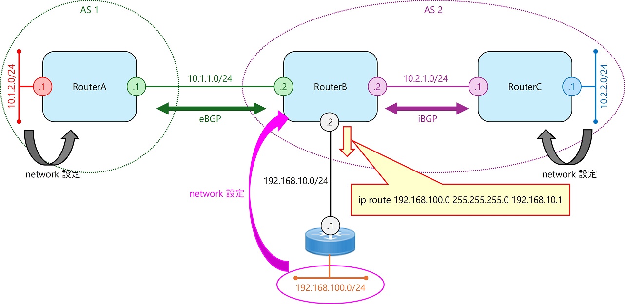
- RouterB 背後のネットワーク 192.168.10.0/24 は RouterB の Loopback インターフェースで再現しています
追加するコンフィグは以下の通りです。
ip route 192.168.100.0 255.255.255.0 192.168.10.1
router bgp 2
 network 192.168.100.0 mask 255.255.255.0
結果として各ルータの BGP 関連設定は以下の通りになります。
router bgp 1
 bgp log-neighbor-changes
 network 10.1.2.0 mask 255.255.255.0
 neighbor 10.1.1.2 remote-as 2
 neighbor 10.1.1.2 next-hop-self
router bgp 2
bgp log-neighbor-changes
network 192.168.100.0
neighbor 10.1.1.1 remote-as 1
neighbor 10.2.1.1 remote-as 2
neighbor 10.2.1.1 next-hop-self
※networkコマンドのネットワークがクラスフルのためmask表示はされないrouter bgp 2
bgp log-neighbor-changes
network 10.2.2.0 mask 255.255.255.0
neighbor 10.2.1.2 remote-as 2この設定内容の場合の各ルータの BGP テーブル及びルーティングテーブルは以下の通りです。
RouterA#show ip bgp
(中略)
     Network          Next Hop            Metric LocPrf Weight Path
 *>   10.1.2.0/24      0.0.0.0                  0         32768 i
 *>   10.2.2.0/24      10.1.1.2                               0 2 i
 *>   192.168.100.0    10.1.1.2                 0             0 2 i
RouterA#
RouterA#show ip route
(中略)
      10.0.0.0/8 is variably subnetted, 5 subnets, 2 masks
C        10.1.1.0/24 is directly connected, Vlan11
L        10.1.1.1/32 is directly connected, Vlan11
C        10.1.2.0/24 is directly connected, Loopback0
L        10.1.2.1/32 is directly connected, Loopback0
B        10.2.2.0/24 [20/0] via 10.1.1.2, 00:35:21
B     192.168.100.0/24 [20/0] via 10.1.1.2, 00:04:24
RouterB#show ip bgp
(中略)
Network Next Hop Metric LocPrf Weight Path
*> 10.1.2.0/24 10.1.1.1 0 0 1 i
*>i 10.2.2.0/24 10.2.1.1 0 100 0 i
*> 192.168.100.0 192.168.10.1 0 32768 i
RouterB#
RouterB#show ip route
(中略)
10.0.0.0/8 is variably subnetted, 6 subnets, 2 masks
C 10.1.1.0/24 is directly connected, Vlan11
L 10.1.1.2/32 is directly connected, Vlan11
B 10.1.2.0/24 [20/0] via 10.1.1.1, 00:32:48
C 10.2.1.0/24 is directly connected, GigabitEthernet8
L 10.2.1.2/32 is directly connected, GigabitEthernet8
B 10.2.2.0/24 [200/0] via 10.2.1.1, 00:34:00
192.168.10.0/24 is variably subnetted, 2 subnets, 2 masks
C 192.168.10.0/24 is directly connected, Loopback0
L 192.168.10.2/32 is directly connected, Loopback0
S 192.168.100.0/24 [1/0] via 192.168.10.1RouterC#show ip bgp
(中略)
Network Next Hop Metric LocPrf Weight Path
*>i 10.1.2.0/24 10.2.1.2 0 100 0 1 i
*> 10.2.2.0/24 0.0.0.0 0 32768 i
*>i 192.168.100.0 10.2.1.2 0 100 0 i
RouterC#
RouterC#show ip route
(中略)
10.0.0.0/8 is variably subnetted, 5 subnets, 2 masks
B 10.1.2.0/24 [200/0] via 10.2.1.2, 00:34:36
C 10.2.1.0/24 is directly connected, Vlan2
L 10.2.1.1/32 is directly connected, Vlan2
C 10.2.2.0/24 is directly connected, Loopback0
L 10.2.2.1/32 is directly connected, Loopback0
B 192.168.100.0/24 [200/0] via 10.2.1.2, 00:04:52上記から RouterB の BGP テーブルに追加した network 設定で指定した宛先(192.168.100.0/24)宛のルートが追加され、RouterA、RouterC に追加されたルートが広報されていることを確認できます。
スタティックルートを BGP テーブルに追加するためには対象スタティックルートがルーティングテーブルにインストールされている必要があります。仮に RouterA のインターフェースがダウンして対象スタティックルートがルーティングテーブルから消失した場合、該当ルートは BGP テーブルに追加されなくなります。
参考資料
- IP ルーティング:BGP コンフィギュレーション ガイド(Cisco IOS XE Gibraltar 16.10.x 向け): 基本 BGP ネットワークの設定
- Border Gateway Protocol(BGP)のよくある質問の調査
Cisco (IOS一般) 関連記事一覧
- 基礎知識
- OS バージョンアップ
- 基本設定
- 管理系設定
- インターフェース
- ルーティング
- コマンド解説
Cisco Catalyst 9000 シリーズスイッチ関連記事一覧
- 基礎知識
- スマートライセンス
- ルーティング
Cisco Catalyst 1300 スイッチ関連記事一覧
- 基礎知識
- 管理系設定
- インターフェース
- スパニングツリー
- ルーティング
- アクセス制御
- その他機能
- 参考資料
Amazon で買えるおすすめアイテム
以下は Amazon アフィリエイトリンクです。ネットワーク作業向けにそこそこおすすめなアイテムです。


コメント